The past few weeks have seen considerable progress in the development of our revised Four Zoas schema. As we expand our sample set of objects, we’re testing our XML structure in new situations and uncovering new complications. The good news: our <stage> approach to modeling layered revisions in the manuscript has held up well when applied to these new objects. Whenever difficulty arises, it’s the usual editorial problem of reading a messy manuscript. But the bad news: our <zone> element has struggled to keep up.
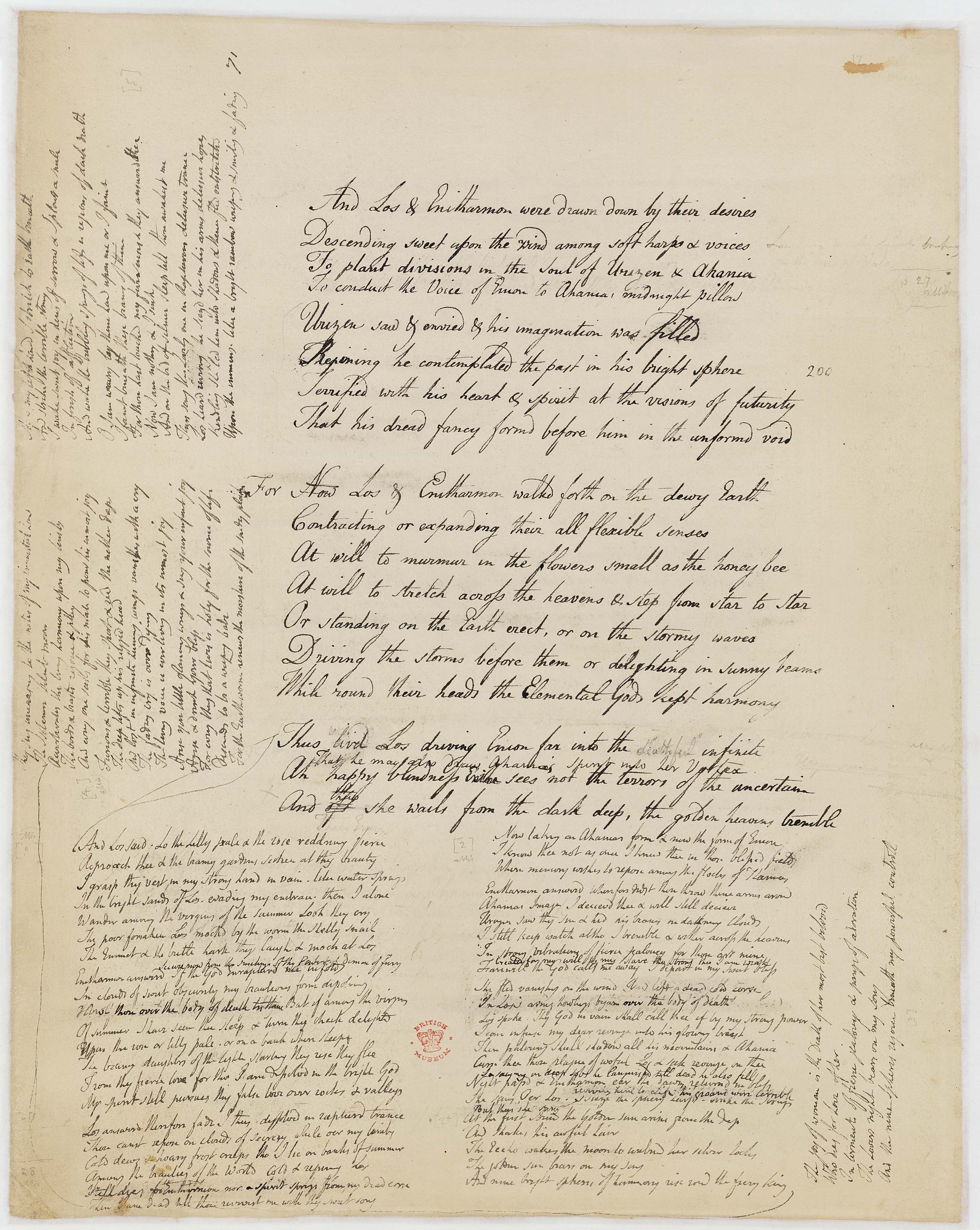
As you can see in our original test object below, the textual layout of the page is predominantly centralized–meaning, most of the text is contained in a central body with a few marginal inscriptions.

To ease the encoding of these discrete textual spaces, we used the <zone> element with @type=body, @type=right, @type=left, etc. Unfortunately (and we knew this was coming), Blake’s marginal inscriptions in Four Zoas are, well, not always so marginal.
Here is object 34:

While the semantic distinctions (body, left, right, etc.) are clear in this object, the amount of text coupled with multiple line groups <lg> in each zone push our descriptive schema to the breaking point, especially when we begin to consider how a display transformation might operate on disparate textual layouts that are–at the level of encoding–indistinguishable from each other. In other words, how can we increase our specification of <zone> beyond our @type’s?
We returned to TEI’s Representation of Primary Sources module, from which we adopted our use of <zone> in the first place. There we figured that if we added a two-dimensional coordinate system to our <zone> attribute list we could create multiple zone elements with the same @type that would still allow for transformational flexibility through the distinguishing coordinates. Simply put, we’d encode line groups into little boxes.
And with the help of an Oxygen plugin that Laura discovered at DHSI last summer, make boxes is exactly what we did. The plugin works by the user drawing a rectangle on an image and Oxygen generating pixel coordinates inside a <surface> element. With some quick adjustments, we can encode our zones like this (just an example):
<zone type=”left” ulx=”756″ uly=”468″ lrx=”2140″ lry=”1208″>
Each <zone> element is specified through pixel coordinates that refer to a rectangular space on the corresponding facsimile image, which encloses any selected set of transcribed text. Thinking ahead, if we wanted to create non-rectangular zones, we can switch out the @ulx, etc. coordinates for @points, which allows for irregular polygons.
Thinking ahead even further, using the coordinate system may have tremendous benefits for our dynamic transcription display. By specifying sites on the facsimile image and connecting them to the transcription, we could, for example, enable rotations for each zone, allowing readers to flip not only the image, but a single zone’s transcription as well. (Helpful for when Blake writes vertically.) The pixel coordinates could also be used to create hot spots on an image, enabling mouse clicks on a zone box to take users to the correct spot in the transcription. Some projects are already making good use of this functionality–the Moore Archive, for example, offers a taste in their recent beta launch. (We’re also enthusiastic fans of that nascent project!)
And hey, something tells us that this approach could come in handy with that looming marginalia project…
—
